Maribel Eco Systems
My Stationary Engines Etc.
Blackstone Engine
My Blackstone has been sold. It was getting a bit too big and heavy for me, but before it went, I took a video of it with me describing the operation etc. and method of starting with a few minutes of the engine actually running at the end.
I hope you enjoy it as it is now on You Tube:
Plus many other mechanical things which include but are not limited to:
Solar Panels, An Old JCB, Atlas Copco compressor, My Old Herbert, 65 Kva Alternator Project, Denbigh Milling Machine, Repairing an Old Sawbench, An Old Plough, Lister Lister Single Cylinder Diesel and Witte Horizontal Twin Diesel
Blackstone Engine Chapter 1 & 2
The Carbide/water Acetylene Generator
My activities are roughly in date order starting from the most recent with older posts towards the bottom (click links to navigate).
Stop Press: I now have solar panels on the roof of my workshop. A 4KW array consisting of 16 individual panels.
I shall get a suitable platform, from which to take a photo of the array, but here is a photo of the inverter, when it was first installed. It now shows a whole lot more KW hrs generated, which will be coming off my electricity bill next month!
After more than two years of use, I have found that the Feed In Tariff actually comes to within a few pounds of paying for the whole of our electricity bills for two sheds and our house. But only in May, June, July and August

More Distractions:
I have an old JCB.
It is a 1976 2D if you know your JCBs. I have been playing with it for years now, but recently I have noticed that when digging, the Back Acter (I don't know why it is called that, either) which actually clips on to the back of the tractor unit, was moving a lot when you took a big bite of dirt. I just happened to meet someone at a rally who had a similar machine and he showed me how it came off completely, rather than waiting for it to fall off.
This sounded like a very good idea, as I could see that there was a lot of wear in the mechanism that held it on and it struck me that if it came off when I was using it, it might make a bit of a mess. Taking the digger unit off, in order to get to the two huge pins that held it on was quite a job. stand by for all the trials and tribulations!
I sought help in the Google Groups, where I have found there are loads of experienced people who are willing to comment on various problems I have had. I may add that I was trained in Electronics in the RAF, followed by Navigation, with Decca Navigator Co. followed by Computers in various shapes and sizes from 1969 until I left full employment in 2002. I was always willing to go beyond the call of duty and so have picked up all sorts of skills over a long and very interesting career.
Here is a transcript of the help I received:

I got a lot of ideas from this group when I couldn't remove the steering wheel some time ago. Over the years I have been using the machine, I have become more and more concerned with the amount the back actor moves when I try and dig a big spade full. it is not moving where the clamps hold it but where it comes off the back of the JCB. There is so much movement that I a bit afraid that it will all fall off one day,- or worse come off one side, if it fell off both sides, I could at least get at it.
The pins that hold it on are probably rusted up solid, but there is play in the socket at the top due to wear and this allows it to rattle about at the bottom too. The answer is to get it off and rebuild the pins and adjust the linkage so that is clamped tightly. However it is totally inaccessible. I have used my high pressure water jet to get as much debris out of the space where I know the pins must be and I have used oxy/propane on the foot control which is supposed to release the pins, but it is all solid. A week or so ago, I got the pin on the
chain out but I cannot budge the pedal. Today I have sprayed a mixture of oil and petrol into where I think there may be bits, which are stuck, but it is all guess work and so far I have not been able to shift anything.
Tomorrow, I shall get a block and tackle onto it and see if it will shift, but even if it does, there is no guarantee that the pins will release. I am wondering if I drill a big hole from the top of the socket down to the pin, I can drift it down far enough to release it as if I can get it all off I can do any repairs necessary. I am also thinking of cutting through the lower supports, but access is a problem there too.
Does anyone still know anything about this? Any comments will be welcome.
Why not phone JCB themselves or their local outlet? I have had advice on an ancient 3c from the depot at Hemel Hempstead.
Explain you need technical advice on an old machine. They can usually find some ancient fitter in the workshop who knows the answer.
I currently have an extending dipper machine here. My problem is that
the clamps don't release!
regards
--
Tim Lamb
I did just that and although no one knew how I could do it, I did get a parts list diagram showing the location and shapes of all the
components. Not exactly where they are though, unfortunately, as I still think drilling down to the pins might be the way, both to get
oil into the right place and to be able to bang down on them effectively.
I am going to have another go at it today and see what I find out. Now the oil has had a chance to soak in I think I shall try jacking
the back actor up and down to try and shake it loose, also get a puller on the foot operated lever and see if this will budge. At
least with that, it is easy to get at and could be the first thing that I can get free.
Regards George.
This morning I got a 4 ton puller on the foot pedal and quite easily moved it up till it lined up with the hole in the shaft. I still have
not got the pin back in to lock it, as the pedal has to be moved along a bit. After the water blasting I can now see more and in the bright of day I can actually see the bottoms of the spring loaded pins that hold the whole of the back actor on. I can also see the bolts that hold the actuators onto the shaft, but someone has wrapped a couple of the hydraulic pipes which pass through in the same area to work the rear jacks with plastic sheet and this was hiding things, so with all the crud, rust and dark, I did not see this before. I may even be able to release the actuators, if they are not too rusty - or else cut them out. Then - now I know where the pins are I may be able to drill down to get to the tops of them and hammer them down with a drift. I am a bit more optimistic now, in any case. It is still a bu**er to get at but maybe----.
I shall have to leave it till Monday now though as I have other things
to do over the weekend. George.
Mine has 4 double acting hydraulic clamps which grip the cross rails and clamp the backacter in position. There is a huge bolt locked with a split pin on each which looks like some sort of adjustment. JCB 3C3 according to the plating. I could do you a photo tomorrow morning but after that I am tied up. This doesn't sound like the sort of problem you are struggling with
though.
regards
--
Tim Lamb
Hi Tim, The 2D has the four clamps too, but there is a tap on the left side of the rear control panel looking backwards that releases
them. When the system is under pressure you cannot operate the tap, of course if you stop the engine the clamping pressure falls and the tap is there to prevent it rising when you start the engine so the backactor can be moved along the rails. This does not seem like your problem though.
The clamps can be removed altogether quite easily, if you have a big enough socket or whatever. I have had leakage problems only with mine and I have found that bypassing the leaking one with an adaptor or just blanking the pressure feed pipe, enables continued use with the remaining clamps. There is a place in Norwich called CES who can mend leaking clamps, they have a big plastic seal inside, but sometimes the body of the clamp leaks, this seems to be fatal and new clamps are not exactly cheap.
Just remove the split pin and undo the big nut and two (or one, - on the last one) pipes and the clamp (on mine) comes off easily.
JCB have got handbooks which are quite cheap which explain basic operations fairly well, but the number of people who actually know is falling rapidly.
Regards George.
Update: The pins holding the rear digger to the back of the JCB are now free but they are being prevented fromdescending further by the forked actuators at the ends of the release shaft, which is where it is stuck now. The shaft passes through bearings at the sides of the rear walls and even though I have heated these up with my oxy/propane and soaked them in WD40 etc. they are still stuck there. The foot lever is quite strong and I have tried winching this free without having the pin through it and the shaft, but as soon as I put the pin in it is not able to move. I can see the bottoms of the fat pins and although they are spring loaded up into the socket, they are free now. I don't know how far the pins have to come down to release the back actor. Just before luch today I heated the area through which the shaft passes on either end of it and soaked it with more WD40, I am trying to gradually worry it free with a lot of forcing it up and down. As a last resort I may have to cut through the shaft and free the ends one at a time or drill down through the cups and try and drive them down with a heavy drift.
If anyone has any suggestions that may avoid these two alternatives, I would be very glad to hear them.
Regards George.
I was in a store yesterday that deals in JCB spares and was lucky enough to be introduced to one of their oldest employees. It was a delight to be able to explain what I was trying to do to someone who had already experienced problem and
understood everthing I said. He said that if I kept on heating and worrying it it must come free in the end, it is the thickness of the
bulkhead through which the shaft passes, conducting most of the heat away, but he also said that when faced by a similar problem on an old machine he was involved with, in the end, they had welded it all together forever. A bit drastic, but it worked and it is an option.
I suppose I could weld heavy brackets to both the sides of the problem so it could be bolted together rather than welded. It seems like giving up on the problem and goes against the grain, but I do need to use it and it is pretty simple, effective and very cheap. I tried to hammer on the ends of the shaft with a drift, yesterday afternoon, just to see if I could move it a bit laterally, but it was very
difficult underneath the wing with a sledgehammer in one hand and a long heavy drift in the other. At least I could get a straight swing at it and If someone is passing by Norfolk today, another pair of hands would be handy. (pun!) When thinking about welding, I have just had another thought: What if I weld another "footpedal" at the other end of the shaft? this would have two possible advantages. I can position it so that I can pull or push on both ends at the same time and the amount of heat generated by 100 amps of welding current, in the shaft near where it passes through the left hand bulkhead, will maybe help free it in any case. At the moment the torque that I am applying to the right hand end via the foot pedal is being lost in the springyness of the shaft, If I get nearer to the problem it will be a lot more effective. I like it! It is quite out of the way so I wouldn't even have to remove it, however with the back actor, (or it it called an acter, what does that mean anyway?) off, it would be very accessible anyway.
So that takes care of this morning. I will have to find and shape a suitable piece of steel and weld it on. Very do-able. Thanks for
listening. It's called brainstorning you know.
Update Tuesday 4-10-11
Welding did not work. Not so do-able as I thought. It is just too inaccessible and after several attempts I gave up. There was not
enough room to weld properly, Maybe if I could have got the shaft out in my vice and concentrated on a really good weld, but after pulling it off far too easily to be anywhere near to what sort of torque I wanted, I went back to a big stillson wrench at both ends of the shaft. and a sledge hammer on the pedal.
I pulled the shaft up first to see if I could just break the lock of the rust, but only succeeded in breaking a medium sized Chinese stillson. Because of the anti-roll roof that I had put on there was a straight line pull if I tried to move the shaft in the direction of the footpedal going upwards, i.e. going the opposite way to releasing the pins. Then I got hold of an old climb jack that came with a 2 ton Cadillac that I owned once and fixed this via a stillson to the left hand end of the shaft and chained it to one of the strong members that I had fixed to the deck for mounting the anti-roll frame. Pretty strong. this gave me a push down on the end of the stilson. It seems like a really strong push and quite stable. Then I got a another stilson and chained a block and tackle to the end and pulling on a slot on the floor plates got quite a good pull from that too. Then using a sledge hammer on the foot pedal I tried to turn the shaft to release the pins. I did manage to move it a tiny bit, as I can see the hole in the shaft is now not in line with the locking hole in the flange on the bulkhead. I got under the side and tried to lever the actuators down, but they did not move much.
It is not enough to lower the pins enough to release the back actor, though and I don't know how much further I will have to go, so I have just given up again and sprayed WD40 in all the appropriate places, come home for lunch and I shall reposition the various pullers and pushers and try again, later. If I had known how hard this would be I would have welded it all up, but now - after so much trying, I am determined to get it off and repair it so I can get it off and on
again easily. I will certainly not wait 40 years before I try next time! I think there will be quite a lot of repair work when it does
finally release as I have been levering and banging away for 5 days now. At least I shall be able to get to it all, although the complete removal of the shaft with all the remains of my welding attempts on it, will not be simple, it may be easier to fabricate a new shaft. I could even improve it with strong turning points built in to both ends.
Regards George.
Update Tuesday 4-10-11
Welding did not work. Not so do-able as I thought. It is just too inaccessible and after several attempts I gave up. There was not
enough room to weld properly, Maybe if I could have got the shaft out in my vice and concentrated on a really good weld, but after pulling it off far too easily to be anywhere near to what sort of torque I wanted, I went back to a big stillson wrench at both ends of the shaft. and a sledge hammer on the pedal.
I pulled the shaft up first to see if I could just break the lock of the rust, but only succeeded in breaking a medium sized Chinese
stillson. Because of the anti-roll roof that I had put on there was a straight line pull if I tried to move the shaft in the direction of
the footpedal going upwards, i.e. going the opposite way to releasing the pins. Then I got hold of an old climb jack that came with a 2 ton Cadillac that I owned once and fixed this via a stillson to the left hand end of the shaft and chained it to one of the strong members that I had fixed to the deck for mounting the anti-roll frame. Pretty strong. this gave me a push down on the end of the stilson. It seems like a really strong push and quite stable. Then I got a another stilson and chained a block and tackle to the end and pulling on a slot on the floor plates got quite a good pull from that too. Then using a sledge hammer on the foot pedal I tried to turn the shaft to release the pins. I did manage to move it a tiny bit, as I can see the hole in the shaft is now not in line with the locking hole in the flange on the bulkhead. I got under the side and tried to lever the actuators down, but they did not move much.
It is not enough to lower the pins enough to release the back actor, though and I don't know how much further I will have to go, so I have just given up again and sprayed WD40 in all the appropriate places, come home for lunch and I shall reposition the various pullers and pushers and try again, later. If I had known how hard this would be I would have welded it all up, but now - after so much trying, I am determined to get it off and repair it so I can get it off and on again easily. I will certainly not wait 40 years before I try next ime! I think there will be quite a lot of repair work when it does finally release as I have been levering and banging away for 5 days now. At least I shall be able to get to it all, although the complete removal of the shaft with all the remains of my welding attempts on it, will not be simple, it may be easier to fabricate a new shaft. I could even improve it with strong turning points built in to both ends.
Regards George.
I cannot believe that with two big stillson wrenches on each end of the shaft being pushed down with one 2 ton lift jack and pulled down by one 1 ton block and tackle, both trying to turn the shaft in order to release the two big pins, which are quite free now, AND a third pipewrench also on the shaft being hit with a sledge hammer, the shaft will not budge. I thought it had moved a bit but on second thoughts, I think it has been welded up to prevent it loosing the back actor at some time in the past. I can't see where, but this must be it. There are the remains of a lot of welds in the area suggesting that it was welded up on a permanent basis at one time, but all the welds have been ground off. leaving it still suspended on the rather loose pins.
I think some one else has been along this path and has got it off but didn't want to get it off again. I found that by using a long 3/4 "
rod I could get at the bottom of the jaws on the shaft and so I have been trying to turn the shaft by banging on them too. I have bent the actuators a bit, but the pins have still not descended enough to release the back end. It is all very heavy duty stuff.
The next step will work! I am going to cut off the bottom actuator levers. They are visible through a gap in the frame. I have drilled
a 1/2" hole down through the frame in which the right hand pin is located and I can press the pin down, but it still stuck, although I tried to hammer on the pin to bend the actuator down further, so it would release, but it won't, so - I shall cut them off. I shall probably cut the shaft out too and use a different method of locking it all in place. Once the back actor is off I shall be able to get to
everything.
As the frames of the back actor and the frame of the back end of the JCB where they come together are both of 1/4 " steel, I shall use a couple if bits of heavy angle to fabricate a bolt together join in the area and probably use the pins too, bolted in the up position, so I can unbolt it easily to get it apart again easily without all this drama of the last week.
I shall add a quick update when it is off.
Regards George.
10-10-11. Around lunchtime, anyone with their doors open in Norfolk would have heard a very well deserved whoop of delight as the digger section finally parted company with the tractor section of my JCB. After another 4 hours Saturday and about 4 this morning, I got the pins down far enough to release the back actor. Saturday I had cut away the lower actuators so the pins could come right down. It was impossible to see what I was doing and it took a lot of fiddling with the gas cutter to get it all out of the way. They were two pretty substantial bits of metal and I wanted to preserve the pins intact to reinstate them. They were still springloaded up into the sockets, so I had to drill 1/2 " holes down to the tops of the pins to drive them down against the springs. Even then , it was not easy, as the back actor frame had to be manoeuvred into the position where the pins were not trapped and so free to be pushed down. Both had to be pushed down together as well to release it. not an easy job with only one person.
When the pins were both down far enough and the frame was lifted by the legs, I pulled it back with the digger and away it came, for thefirst time in several decades, I would say. It was fairly straightforward after this and I was able to park it on stands and drive away a bit, then disconnect the pipes. When the pins finally came out, I found one had been broken a long time, Now the question is, how do I put it back together using a design that does not allow the back actor to move about when I dig and yet will still allow it to be taken off without using the stupid foot release, that I still have to cut out of the frame, - as it is still absolutely frozen. But I can get at it now so there is no real problem.
Tomorrow I intend to clean both areas that are now accessible, clean up all the oily tools that I have been using and think about how to do it.
Winter/Spring 2011.
As I was having a bit of trouble with my lathe, which I needed to rebuild a beefier centrifugal clutch for my heat and power Perkins set, I decide to have a short rest from it all and rebuild a smaller Kubota diesel set of some 6 Kw. It had an air cooled engine, but was easy to convert to water cooling and I stripped it all down and rebuilt it all - taking the opportunity to sand blast and paint all the bits and make it all mobile, so if the mains went off at home I could tow it about easily.
[IMAGE NOT FOUND]
The engine had a peculiar water condensing radiator affair for cooling, but as I wanted to harness all the heat, I took it all off and ran the water directly through the block using a central heating pump, which controlled by a thermostat and driven by the electricity generated, it is arranged to either go through a little electric motor driven heat exchanger at the back of the generator or sent externally to a central heating system, should this be required.
I have also got the bits to make a water cooled manifold and exhaust pipe to harvest this waste heat too.
It all looks nice and rides well on the trailer.
Distractions Sept 2010
After the normal summer grass cutting and maintenance, I have finished a quick project. In one of my sheds, I rediscovered a rather nice 2 stage Atlas Copco compressor that has been crying out for attention for about 30 years. So I attended to it. I bolted on an old 1/4 Hp. electric motor and away it went, the motor running out of steam at about 300 psi. It needs a pressure release valve and a pressure switch, but that is easy enough.
My old Herbert is playing up and I have been given a dial indicator which has proven to be very useful and also proven that the scroll is worn, as I get different amounts of run-out at different settings of the scroll. Below are some pictures of another chuck that will fit on the lathe with the diameter of the recess that holds the chuck concentric after the 3 studs are use to pull it into position. Has anyone got anything like this, preferably a 4 jaw chuck. as I have 2, 3 jaw chucks that do not work properly. However - anything considered.
Above the back of another chuck that fits OK.
Size of the flange that supports and locates the chuck
The chuck on the lathe with lots of run-out from a worn scroll.
Current Projects. 65 Kva Alternator Project.
27-04-10
After a number of interruptions that I shall not go into now I have managed to get a centrifugal clutch working. It is not perfect but I can improve it, and it does what I want. It allows my engine to start without having to turn the massive rotor at more than engine speed, locks the drive at full speed and runs at the governed speed without slipping and disconnects the alternator as soon as the engine is stopped.
On and off it has taken nearly two months. I have looked at hundreds of governor designs and trial-and-errored four different ones
This was the first one that actually worked. It was not strong enough and I beefed it up, got better springs and removed the nut and bolt weights that I had thought would be necessary. I tried using it in the leading and lagging positions but ended up with a more or less lagging position, i.e. the friction edge of the brake shoes were behind the pivot point. Fairly strong springs now pull it away from the drum as soon as the speed drops when the engine is shut down.
27-2-10
I think this is getting near to the design for the drive that I shall use, the problem with this is the load on the starter of the huge rotating mass of the armature which has to be started as well as the drag of the very cold oil-filled engine with quite good compression and no help from glow plugs or exhaust lifters etc. It might work when the weather becomes less glacial.
25-01-10
Here is the starter bolted on and a shaft just stuck on the flywheel and a support bearing to see how it will go. The channel bolted to the base has also now got fillets welded inside to stiffen it all up, which is now satisfactory. I am now building the flywheel flange and it runs very nicely at 1000 rpm, so I need a pulley fitted to the new 1 inch shaft of about 1:1.5 ratio to give me 1500 rpm on the alternator, i.e. as the alt. pulley is 5 inch I will need a 7.5 inch pulley for the shaft.
The arrangement below is better from the vibration point of view, but the 4 inch channel support is still not very rigid. I can't lower the Perkins more as the flywheel starter ring will foul the frame. I do not want to weaken the frame by cutting out slots for this.
Next step I think, either weld up the channel and/or fit square section of a heavier gauge. or weld in cross pieces between the two sides.
That is what I did! Much better.
This is the rear plate ready to be drilled - or rather marked out to fit on the engine to provide a stronger rear support and to mount the starter on. I made a cardboard template and I don't think that any hole was more than a mm out.
7-2-09
The flange to connect to the Perkins - or to it's flywheel is a bit of 1/2 inch sheet cut round and a hole machined out to fit the shaft This is the flywheel and the round flange before I started on it. I have now welded it to the shaft and I'll take another photo when it has been cleaned up and drilled as appropriate. I wasted weeks in making the in-line drive, only to scrap it at the end.
This is half of the in-line flexible coupling. I had to make a bit of shaft the same diameter and with a suitable key and keyway to join up with the flywheel flange on the Perkins. Here is the shaft being turned down in my old Herbert Lathe, after I had cut the keyway on the Denbigh Mill.
I made the key with an old bit of 3/8 X 5/8 scrap.
Months later, in fact it is now nearly Christmas. The machine had to be dragged outside as a lot of other jobs came up over the summer. Now it is inside again and even though it is freezing in the workshop, I am still thinking at home about how I am going to do it.
I got it running, but was unhappy about the vibration. It may be that the engine supports and cushy foot mounts are not rigid enough and I shall have to rethink the engine mounting.
The engine I mounted on a strong frame - which I shall have to strengthen further by cross bracing, as it wobbles from side to side a bit. It is lined up with the alternator and at present it is in between guides so I will be able to slide it back and forth to get the coupling I am making in. I may do without the flywheel as the alternator acts as one anyway. I shall see how easy it is to start on the starting handle, if it proves difficult I will have to find a way to fix a non-Perkins starting motor to it some way. The flywheel has a starter ring on it, but it will not be easy.
It is a pity the arrangement above did not really work. It was too fast for the engine, being in-line and the whole thing vibrated appallingly. It would have shaken itself to bits very quickly!
Work has progressed and I have mounted the alternator and an old Perkins P3 engine on a frame that I welded together using two bits of thick I section. I mounted it all on castors so I can move it about a bit to get it under a strong roof support in my workshop. I can also pull it all outside onto the drive, if I want to get anything else in or out.
5-11-2008
There has been quite a lot of info. posted to the Google Groups etc. I shall paste it here and anyone who likes to comment or suggest anything is more than welcome to email me. Really good info will be displayed for others with similar problems.
First sight of it for many years, This is just after I lifted it out on the front end loader of my Fordson Power Major.
Here is a transcript with further detail:
I have had a very big 3 phase 415v 50 c/s alternator for years now and at last I need to put it into service. It was manufactured by Mawdsley in the early 80s and when I shut it down, I disconnected the AVR too and kept this and the spare I held. I have checked with the Company and there is no way that they can help me with the excitation to fire it up. Before I go to all the trouble of connecting it up to a diesel engine and spin it up to 1500 rpm, can anyone please tell me a few things about it.
It has a separate excitation generator on the end of the shaft and I would imagine that this is still in circuit, as I have not been inside
it yet. How does this set up actually work. does the alternator self excite and the AVR just keep the output within narrow and automatic limits? Will it produce 3 phase on it's own or is the AVR essential and in this case is it a standard wiring circuit or will it be unique to this alternator and AVR setup?
There is quite a lot of information on the makers plates on the two units, but no information on how to connect it all up. The AVR itself has a whole lot of wire connections available but nothing to tell me what goes where. I have spent hours looking for information on the web, but with no luck. This is what I wrote to the manufacturer: The reply was a bit negative
so I have left it out Thanks for any comments, It really is a super machine. a bit dirty now but that will be easy to rectify.
Regards George.
I have had a closer look at the big alternator - which is the one that I really would like to see working again. There are two units, the main alternator body which has the following information:
Mawdsley A/C Generator BS 2613?70 (there is a scratch across the number)
ser. no. 4FA4KB. 501
KVA 65 ( I thought it was 85, but this is better really as my engines would be struggling at 85 KVA.)
Volts 415. Amps 90. 3 Phase. conn. star. rpm 1500.
Excitation volts 71. amps 18 pf. 0.8 enclosure SP?
Then on the excitation generator there is another label:
Exciter BS 2613/70
No. 6R4N3155 rpm 1500 volts 71 amps 18 3 phase hz 50.
Exc. volts 16.5, amps 1.8, ins. class F.
I have two identical voltage regulator boxes made by Emrec but with your Co. name on too. Type 4VR ser. no. 1197 (one of them) 30 VDC. 6 Amps.
I am not sure about this, but am I correct in assuming that the voltage regulator feeds into the exciter and this is internally fed into the main alternator? If so and if the 4VR is the one for this alternator, then all I have to do is wire it up and I do have the connections for the 400 Hz alternator to another voltage regulator 6VR I think they are, I have two of these too. I have a small number of explanatory sheets in how the 400 Hz machines work with their AVRs If you can confirm the 4VR is the one for the
65 Kva 50 HZ machine I think I will be OK.
Hoping this makes sense to you and that you can shine some light on the situation. I wish I knew more on how excitation works - or worked 30 years ago! Would it be true to say that most alternators use the same sort of excitation, and only the details are different between manufacturers?
If the voltage output of an alternator is only dependant on the loading and the DC current being fed into the excitation winding of the exciter, it may be that I can build a circuit that does this in a very simple way. My load is not going to be anywhere near 65 Kva in any case.


[IMAGE NOT FOUND]
A simpler set of connections could hardly be imagined.
This is with the exciter cover off.
[IMAGE NOT FOUND]
The external exciter box contents is shown below.
[IMAGE NOT FOUND]
I think that this is going to be too complex for my purposes! Hopefully I can make or purchase one that is much simpler.
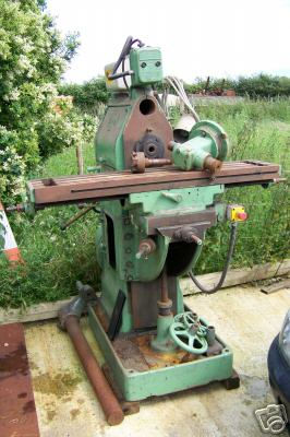
My Denbigh is now functioning as well as can be expected. I shall have to look on Ebay for a big, strong, heavy duty, milling vice, as the ones I have are both toys for a machine like this. The horizontal milling wheel support bar is now fitted and I have found a selection of milling wheel and slitting saws to fit the 1 inch shaft. I am not very good at sharpening them yet though.
I just bought this Denbigh milling machine. It is over 50 years old, but looks in quite good condition. Getting it home was a bit of a saga and I have just set it up on a stand, with heavy castors, so I can shift it about if necessary and connected power to it. This is the advert I first saw.
This is it in my workshop, I have started to clean it up. The vertical mill gearbox located OK and it has a scale on it showing the rotational position, but I cannot see how to lock it. If you get hold of it it just rotates.
Views (from left to right) from the left hand side, right hand view, the vertical drive gearbox, view of left rear.
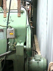
Part of over arm, showing bearing supporting horizontal shaft, which I do not have and may have to make, any suggestions?
At the moment I am trying to find out what locks the horizontal to vertical gear box in position, I got it bolted on and the through bolt tightened up the drive, but the housing all rotates. Any ideas?
The keyway for the drive pulley on the sawbench below is waiting for the milling machine above to become operational, to cut a keyway on the diesel engine output shaft. It is all but finished, apart from this.
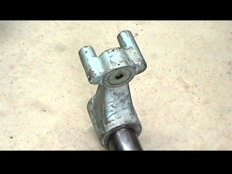
I am in the process of repairing an old sawbench. It has an ACROW name on it and there is a problem with the saw blade attaching bolt - it is a left handed thread and it holds the blade in a shaft with a large boss with a pin in the end to locate the blade. The head of the bolt has sheared off and it is too short to weld another on. The bearings could do with either replacing or cleaning and re-oiling, but even though I have removed all the things that would allow the bearing to come of, it will not move. Any ideas how it is fixed? See below for progress, I now have a LH bolt!
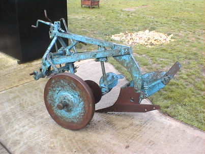
I cannot see anything else holding it all on! There is no recess on the shaft to locate a puller, either. I was asked about the old plough in the above picture so here it is below
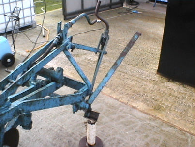
So what is the bit of iron sticking out to the right of the picture? Below. It does not seem to do anything significant.
A friend had a look at the plough and I did try and do a furrow with it but it was digging too deep with the little blade. To make any adjustments I had to dismantle the end of it where the cutting wheel is mounted as it was rusted up and I could only free it all up and clean and grease it by getting the bits in a big vice. I put it back together, but I still do not know where the various bits go in relation to each other.
I hope someone can give me a bit of advice and I have taken a few shots of where the bits are positioned now.
And from the rear of it.
Now - 29th Jan, I have got the collar off. I can't really see why it is needed, I had to make it very hot with a big gas torch and then twisted it with a big stilson
Now I am trying to pull off the two flat belt pulleys, but they will not budge!
I also want to change the flat belt for V belts so I need to get the thing dismantled. How many horse power would a 3 ft. blade require? I have now come to the conclusion that this end does not come off. I think the bearings have to be taken out at the other end.
10th. March. Now I have got all the old pullies off and installed a 3 sheaf V belt pulley. To do this I had to make up a big Channel puller and also fit a new chuck on my lathe, repair a horrendous amount of play in the cross-slide and re-position the capstan saddle. Next, I've got to get at one of the engines which is right at the back of my workshop and which weighs about 1/4 of a ton! It is about 15 Hp. so it should be OK.
Lister Single Cylinder Diesel and Witte Horizontal Twin Diesel - Help Wanted
I have this engine in my UK workshop amongst a lot of others. It is a Lister single cylinder Diesel about 5 or 6 Hp. I "collected" it about 20 years ago. This is how it was then and how it is now. My questions. What is it exactly and is it worth restoring? There are a lot of bits missing and I am wondering if they are still available. As far as I remember it was not seized and the crank was straight, apart from that and the obvious missing parts I will have to wait till I find it again as it is in one of a lot of packing cases. What do you think? I would welcome a bit of help here.
Another one is a Witte horizontal twin diesel, dismantled, with no fuel injection pump. One big flywheel. It is about 40 years old, about 20 HP, I would imagine and I put it in a crate with everything cleaned down and greased about 20 years ago. I tried a bit to get another injection pump, but - from the Gulf, I failed at the time.
It is in very good condition and any information on availability of spares from where and is it worth it to begin with, would be very welcome.
Blackstone JP1 and OP1
There is a place about 70 Kms. up the road from here where I have found a little workshop where they specialise in Stationary Engines which are used to drive water pumps for wells out on the desert. He had a few Blackstones there which caught my eye. The JP1 is about 450 pounds, in running condition that is 16 HP. and the OP1 s that he has are about 600 pounds. I do not know if they are collectible enough to ship back to UK at this price, but they are magnificent beasts.
This one, (above) is a 16 HP JP1 It could be almost any age as they were produced for many years, but it is in running condition and there are more where that came from. Below on the left is a 26 HP OP1 quite a bit bigger although it does not really look it. You often see these, miles from anywhere, chuffing away, with a big fuel tank, filled up every few weeks for company. They are pumping water from a deep well - usually for a small plantation far from the electricity supply. They are only used where there is no electricity
A Gaggle of OP1's ripe for restoration.
My First Engine
When I came back to Abu Dhabi in 1972 I was taking our dog for a walk one afternoon and passing a dump I saw an old Cement Mixer. This had obviously passed it's sell-by date, but I could see that it still had, what looked like a very useful engine inside.
I went home for an old boat trailer that I had and, - positioning it under the engine cowl, I undid the holding down bolts and the engine fell into my trailer. Over the next few months I completely dismantled it, inspected every part and wrote away to Petter for the handbook and parts list. It is a circa 1960 PAZ1, - a single cylinder diesel of about 3 HP. and it drives a little 3 Kw. alternator on wheels and is now used for providing portable power.
The Cover of my Handbook
I cleaned and de-rusted every part and painted the cast iron, or polished the brass bits and when I had leave in UK, I ordered all the parts I needed. They were all available (they are not now) and they were brought back to my little workshop, where I was working on it. When I assembled it all again and it started the first time I tried to run it, with no problems, I was delighted.
Everyone thought that I was daft to spend so much time and effort on an old engine, but I had got the bug. I put it on a wheeled trolley and kept it behind the bar in our villa. I used to start it up and all our guests would run for cover as it burst into life with an incredible cloud of black smoke! It was a dramatic conversation piece and when it started it certainly grabbed the attention of everyone in the place.
I never recovered from this and have spend a good chunk of my life working on ever more dilapidated and wondrous machines. I have used many of them and never sold one. I have crates full of old engines in various states of decay, stored in my huge workshop in UK and one day I will get them all restored. I practiced on a number of other small ones before I found the Blackstone. This was an epic engine recovery story.
Executive Summary: When in the Trucial States in the 1960s, there was no main electricity supply. I should say that there was a power station of sorts but the distribution systems did not extend very far. One of the Supermarkets, (Spinney's) - and they were not very "super", in those days, had a generator set to keep their deep freezers and air-conditioning working, (as had nearly everyone in those days) and this was driven by a huge single cylinder diesel with it's own radiator and a belt driven alternator. I am not sure if they were connected to the power station, maybe they were but the generator certainly ran quite often. When I went shopping I used to stop and watch this magnificent machine thudding tirelessly behind the shop in the Abu Dhabi seafront. I left for a few years but when I returned, many years after this, I was talking to an friend who had noticed my obsession with old engines and he told me that the original Spinney's engine was still in a store and had been kept as a standby when the public electricity was reliable enough not to use it continuously and finally retired. As a result of this, I started a search for the Blackstone and in the saga that followed there is almost enough material to write a book. The finding, recovery to my home in Abu Dhabi, and the subsequent shifting of this 4 ton monster to my place in Norfolk, UK was not without a few difficulties. The first time it was exhibited in UK at Tunstead Rally near Wroxham in Norfolk, in the mid eighties, after extensive restoration, it won the first prize in the enclosed crank category!
Just to prove it, here is the first prize rosette, - on the air filter. I had only just got it ready to show at this time and a lot more has been done to it. Note the tiny fuel tank, on a post to the left, - it ran all day on about a gallon of diesel, also with only water in the jacket and no external cooling! You could put your hand on the exhaust pipe and not get burnt. Also note the large Freon cylinders (2) filled with compressed air at about 300 PSI for starting.
Here it is running. There is a temporary exhaust pipe and I had a big problem with the spray of oil that came out of it when it was ticking over slowly. There was not enough work for it to do, to stop the oil working it's way past the rings. When it is under load it is OK. I had to put a piece of wood behind it to catch the oil. Now it has a posh water pipe, all nicely fitted with a down turn at the end and - at a show, I direct this into a cardboard box full of old rag. It sounds like a steam engine when it is running slowly and hardly anyone guesses it is a diesel. The pipes to be connected to a radiator are shown (blocked). It never got hot enough.
Just off for sand blasting (Left below). I had the whole thing done, including trailer, after I had got it running for the first time. Trailer is a really heavy duty construction and probably weighs almost as much as the engine. It has Indespension axel and Land Rover wheels. After sand blasting (Right)
Blackstone. Chapter 1
We were talking about my obvious hobby of rescuing old engines and my friend suddenly said that he knew of a big old one that had been used by his company for many years and had been put into storage, where he had seen it fairly recently. As I knew he worked for Spinneys, I immediately started to wonder.
I pressed him for more details and from what he said it could have been the Blackstone I had admired so many years before. I asked him to find out if it might be available and told him that I was not expecting it as a gift!
Months passed. I asked him from time to time if he had found out anything, but no.
In the end, I asked him and he said we could go and look at it. It was in a warehouse in Mussafah, the industrial area about 20 Kilometres from Abu Dhabi town and actually off the Island. We found the warehouse, but it had obviously been cleared some time before. What the chap working there said, made me more sure than ever that it was MY Blackstone. I found out that it had been sold for scrap, - for a lot less than I would have paid, several months before.
Well, you’ve got to be philosophical about things and so I reluctantly gave up. I never thought that I would see it again. I suppose I was reasonable in this assumption, but I was wrong. My friend Roland who also had an interest in all things mechanical and used to come with me, - or I used to go with him, on tours round all the back tracks of Mussafah, just to see what we could find. The thing we found most often was a punctured tyre as there were all sorts of things lying around where we drove. However one day, we both saw something at the same time. It was a very ramshackle trailer with the remains of a very big old engine on top. I had to look twice, but then of course I was sure. It was my Blackstone. It was – laying, is the right word, almost reclining, outside a little repair shop. Many years had passed since it had been maintained, but it looked complete, or at least nothing major was missing. It had rained a lot in the previous winter and it was up to its axels in hardened mud and really was a sorry sight. The owner of the shop came out to see what we were doing and when asked if it was for sale immediately said no, it was going to be refurbished and sold for an enormous amount.
I told him that it would cost an enormous amount to refurbish and then it would not be sold and he would be better off selling it to me as it was. But no, he was adamant and so after making a note of where it was we gave up again.
Over the next two years I went back every few months and I could see that his resolve was weakening. The last time I went back I said it was obvious to me that he was not going to do anything with it and I would offer him there and then 1000. Dirhams, that was about 200 pounds. I would take it away and if he refused this time he would not see me again. (Liar). His friend in the workshop I could see was keen on getting his hands on a ready 1000 and told him not to be so daft. He saw sense at last and we arranged to come down the next day to collect it.
This proved to be a bit easier said than done. When we looked at the wheels and bearings we could see that it would take a lot more than just pulling it out of the mud. The bearings were not protected and so were full of dried mud instead of grease. A thick towrope behind my Blazer soon got it clear of the mud, we just dragged it, four wheel drive and low ratio. We jacked it all up and except for one of the bearings that had a cap on and looked OK, changed the grease and adjusted them after cleaning them out with petrol. We inflated and mended punctures in three of the tyres. The trailer itself was not very solid, but we guessed it would stand the trip into town. I had a Villa with a long drive and a lot of concrete laid down and could do most things, if we could just get it there. We made a drawbar out of a length of water pipe with a hitch at one end and a fitting for the trailer at the other and after pulling it onto the road with my Chevrolet Blazer, which is quite a strong 4 wheel drive truck, it looked ready for the trip.
We started off very slowly, but as it seemed to run fairly smoothly we picked up a bit of speed. Not much, but it was late afternoon and we had about 20 Kms. to go. Everything was OK until we were going over the bridge across the sea to Abu Dhabi. we were in the slow lane of three. There was suddenly a grinding noise and the left hand front wheel came off the trailer and went rolling across the two lanes to our left, - the fast lanes. Very luckily nothing hit it and the trailer dived down into the road at the front, all three remaining wheels came off the ground and for a heart-stopping moment it looked in my rear view mirror as if the whole lot was going to turn over. It had dug the front left corner of the trailer into the road and although I was sure it would fall over to the left it came back down on the three remaining wheels and ploughed to a standstill gouging a long wound in the road, as it did so. Cars and lorries were whizzing past at high speed and we thought that any moment there would be either one plough into us or the Police would turn up as they always did when they were definitely not wanted.
We retrieved the wheel and as the bearing that we had thought would be OK had completely disappeared, we had to get the wheel on somehow and get off the bridge. It was only three lanes and at this time of day they were all in use. We jacked it up and luckily in my tool box found some big washers that would hold the broken remains of the bearing on long enough to get us off the bridge. The nut that had wound off when the bearing had broken was about 50 yards up the road and still usable. We slapped grease on it and split pinned it back on and although it was all smoking when we got onto the hard shoulder beyond the bridge, - it held.
It was obvious that we were not going to be able to get home on what remained. So what to do? I had a big 21 ft. boat at the time and it was on a very strong low trainer and so we decided that I should go and get this and a tripod I had and a block and tackle and lift it all on the trailer. I unhitched, and dumped the boat onto some soft sand where it would not come to harm and set off back with all the tackle that I could think of, that might be necessary. We took all the old wheels off the trailer and using the frame and a 3 ton block managed to get the whole engine high enough to get the trailer under it. The weight was more than we had counted on and I had to help it up with a big trolley jack that I had also brought. When we had it all hanging in the air on the poor block & tackle that was being grossly overloaded, I wondered if this was all going to be really worth it.
It was getting dark as we finally backed into my drive with everything more or less intact. At least we had not dropped the engine. With the huge flywheel, that must weigh at least half a ton, the crank would have been permanently and irrevocably bent if we had done so.
The next day we removed the old frame of what was left of the trailer and gratefully dumped it. The Blackstone was raised up in the air again and I took all the measurements to give to another friend who had promised to make me another frame that could be used to construct a box around it for shipping and which could also be used as the basis of a strong trailer in future. A couple of weeks later the completed frame with the Blackstone firmly attached, was laying at the bottom of my drive and a box was taking shape round it ready for shipping off to UK.
Once a decent frame had been made I welded some bits of channel underneath so it could be lifted with a fork lift. Then I panelled all the sides in and made a top and filled what was left of the space inside with "useful things". I screwed the top on, painted my name and address on the sides and waited for our annual leave before sending it well in advance. It was calculated to arrive in UK - Felixstowe, about the middle of our leave. I never weighed it all, but it was about 3 or 4 cubic meters of almost all iron and steel. Certainly rather heavy.
Blackstone 2
After spending a couple of weeks boxing up the Blackstone and filling all the empty space around it with other things that I would rather have in UK. I rang up our shipping agent and told them what I wanted. They were used to me and my heavy loads by this time. I had made several boxes with a thick channel base, 2 inch angle iron supports to make a box of 8 feet by 4 feet by 4 feet. This allowed me to bolt sections of 8 by 4 three quarter inch plywood to the sides to make strong boxes. I always left clearance underneath for a fork lift truck to slide its prongs under and always bolted lifting eyes to the top 4 corners to enable me to handle it when it got back. In Norfolk I had a big tripod set up permanently, made of 4 inch thick water pipe and a 4 ton block and tackle which could be fixed to the top and I could get a lorry under this.
Whenever I collected a box that I had shipped home I used to hire either a lorry or a trailer for the day to collect it from Felixstowe, - our closest port. This was about 40 miles from Norwich and if I set off early in the morning, picked up the vehicle I could usually get the consignment cleared, and brought back and at least dropped onto the ground, so allowing the vehicle to be delivered back after only 24 hours, the next morning. It did mean I had to be fairly quick about everything though, otherwise I would incur another day's charges.
Our shipper had no problem lifting the Blackstone box onto the back of a lorry. I had estimated about 2 or 3 tons, but they brought a very large mobile crane, - and, with my name and address painted all over one side, it was soon taken away. I did not see it again for several weeks.
During our summer leave I got a call from Felixstowe Docks to let me know that the box had arrived. As I had my old Landrover running quite well at the time I decided to hire a heavy duty car transporter trailer and tow it myself. I found what I thought was a suitable 4 wheel trailer and early one morning set off for the Port. It was a fairly low trailer, it ran well and I was in Felixstowe by mid morning. There were no problems with the consignment and soon I was waiting in the parking area for the port Fork Lift Truck, - designed to lift Containers to come out with my box. Positioning it over the wheels, the driver carefully lowered the box onto the trailer. This is the moment I realized I had a problem and the box was far heavier than I had estimated!
The box touched the base of the car transporter trailer and the driver lowered it more, The trailer went down on the spring over-rides and the tyres went down to the rims and as he released the lift. The ground clearance under the trailer became tiny. The Landrover was still fairly level so I asked the driver to re-position it nearer the front of the trailer to lessen the weight on the trailer. It helped the trailer, but not much. The Landrover was now at a significant nose up angle and I was glad I had brought a strong vehicle.
I measured the pressure in the trailer tyres, They were all about 25 PSI. I had an electric compressor so I pumped them all up. The tyres looked a lot better at about 50 PSI, but that was really too high. With all the chains and tensioners, etc. I had brought, I made the box secure and had a good look at it all. I did not like what I saw much, but there was not much I could do about it. It was obviously grossly overloaded.
I tried a slow tow in the car-park. It wallowed about like a fat cow. The trailer groaned with every motion. Having no other options except giving up, I did all the remaining formalities and set off. I went a few hundred yards and stopped to inspect everything. Nothing seemed to have broken or was starting to overheat. I have had a lot of experience with the taper roller bearings which were fitted to the trailer. They are very sensitive to having suitable clean grease, to being correctly adjusted and to overloading. None of them were hot, so I gingerly increased my speed, after all, I had about 50 miles to go.
The trailer had no effective springing and every bump in the road was a disaster waiting to happen. There were few road humps on the way out of Felixstowe and it was a fairly quiet day too. The trailer grounded on every thing more than a few inches high, but it had a strong chassis and I could not see this being a problem. The Landrover with it’s 2 ¼ litre engine had lots of gears and was supposed to be able to pull 4 tons. One thing I did notice was that the overrun brakes on the trailer did not seem to be working at all. I proceeded slowly and relaxed slightly once I got to the open roads.
Going round curves was putting a lot of stress on the tyres and just coming out of a roundabout this proved too much for one of them. It was not a wonderful tyre and there was an ear-splitting bang and the trailer suddenly became un-pullable. Luckily I was not too far out in the road, but of course I did not have a spare. There was nothing for it but to jack it all up and I did have (and always do have), a good selection of jacks and tools. It was almost at the limit of my 4 ton car jack to get the wheel up off the ground high enough to undo the nuts to remove it. I had two and some wooden blocks, but I also had to jack the trailer off the towing hitch of the Landrover, so I could go and buy another tyre. In fact, I bought another old wheel too, as well as a new tyre. I could see that if one could not take it then the others – which were all rather hot might do the same thing at any time. The people in the tyre shop, who had a good selection of wheels too, were a bit surprised at my desire to put 50 PSI in it, but they did and I was soon off again.
I was torn between going slowly enough for safety and the desire not to appear to be going so slowly that the Law might think that I thought that I was a potential danger to other road users. I was sure that the trailer jacked up on the side of a roundabout had not gone un-noticed and I did not want to attract any more attention. There was not any doubt that I was illegal in so many ways that I would have been put in clink and the key would have been thrown away should I have been stopped for any sort of check. The brakes on the trailer were non existent, the lights did not work, and it was horrendously over loaded. That was enough to be going on with. In it's favour, the box on the trailer, although extremely heavy, did not really look as if it was a very concentrated weight.
If anyone is familiar with the old A12 North of Ipswich, there used to be a Royal Air Force Station called Martlesham just to the east of the road and at a place called Crown Point there was a very steep hill. I had to come down this hill and I was not looking forward to it on this occasion. At the bottom of the hill was a junction with a traffic light controlling traffic. It did not control me. I was in bottom gear standing on the brakes and – although not going very fast, I was not slowing down. In fact I was steadily increasing my velocity and I could see that the lights at the bottom of the hill were red.
I could smell the smoke starting to pour out of my brakes. I got almost up to the lights and they went green! Pretending that I could have easily stopped, I put my foot down and got away from the potential disaster zone as quickly as I could, as it was now an uphill section, this was not so fast, but it took some time for the sweat to dry. I stopped at a convenient lay-by and had a cigarette. This was the last incident and on reaching my house I had several helping hands to unload the box. It was not easy and it must have weighed about 4 tons, It is amazing how a lot of little things can mount up in weight. I knew the Engine itself was around a couple of tons, but I underestimated the other junk that I put in afterwards.
The trailer was delivered back to the hire company with a complaint about the tyres and brakes, but I did not like to say too much or they might ask a few awkward questions themselves. I did not give them the spare wheel either. They did get a new tyre out of it and when the box had been taken off, the trailer did more or less spring back into position. The upshot of it all was the Blackstone, still blissfully unaware of the problems it had caused me, was still safely inside, surrounded by bits of other engines, tools, motors and no end of spare parts. After I had unpacked it all the real task of restoration and breathing life into this grand old engine again, would begin.
One of the best things I ever spent 400 pounds on was an old Fordson Power Major Tractor. It has a front end loader and most of the non-essential covers and ancillaries have over the years been removed, as they were in the way, or I was afraid they might get damaged. It has a 4 cylinder diesel engine. It needs a very good battery to start it, but what a useful tool it is. I can drag things, I can use it to lift about half a ton on the arms of the front-end loader, - even more if I attach things, so they are close to the radiator and the huge chunks of channel that I fixed to the frame to protect the radiator. I intend to restore this too one day, but most of the time it is just too useful to make it into a show piece. I use it for everything and this is how I got the Blackstone on its frame into my large workshop. The first thing I wanted to do was to get it to run again. I still did not know if there were any major problems with it. It seemed to be straight and its adventures with me had left it still unscathed. However there were more things than just this involved. It did not have as much compression as I would have hoped, but this might be the oil quality or the fact that it had all drained away over the years.
The first thing was to make sure that it was all fastened down OK on the frame. I also bolted the frame to the floor of my shed. I did not want it to “walk” all over the shed, if and when I did get it to fire up. Draining all the oil out was the next job. It seemed to have been looked after very well, which tied up with what I knew. It had been used as a standby engine for many years, and Spinneys would not want it to give any trouble it the mains failed and their food storage was in danger. I discovered a lot about it and although I did not know at that time the procedure for starting it, I did investigate all the parts involved and made sure that they seemed to do what I thought they might have to do.
Because it was a single cylinder diesel, the effort involved to get the huge piston to go over the compression stroke with sufficient energy to fire the injected diesel fuel at the right time, was considerable. It had a single flywheel of some 5 feet across, a massive weight, that, once turning at about 50 or 60 revs per minute would cause the engine to go over compression two or three times, enough for it to fire and get going on its own. Getting it up to 50 rpm was the trick. There was no way that it could be turned by hand. There were holes in the rim of the flywheel for “barring” the engine round to reach appropriate points in the cycle for timing purposes and when using the air start.
Air starting was really the only way to go. I wrote to Blackstone and they sent me a little handbook about operating the engine and without this I would have been really lost. Once I had this I had a good plan of action and although I went of on false trails like trying to use a belt drive to my little Petter engine to start it and heating up the cylinder head with a blowlamp for hours, It was finally by using their procedure that I succeeded.
The problem with air starting was that the engine needed a lot of compressed air, several cubic feet of it, pressurised to at least 300 PSI. This was not easy to get in my workshop and I experimented with many compressors and storage tanks before I was able to achieve this. Someone gave me a couple of refrigerant tanks of about 5 cubic feet each which I coupled together. I also had high pressure hoses made up to couple up with the air port on the engine. In the handbook I discovered that there was a back charging facility on the engine whereby it was possible to use the kinetic energy in the flywheel and by turning off the fuel the valves could be changed to operate as a compressor. The engine was run up to about 500 rpm and then the fuel was shut of and the valve levers changed to “charge” and the engine would gradually slow down but would charge the air cylinders whilst so doing. Of course the problem was that the engine had to be running to charge the cylinders to start with. Mine wasn’t! A small compressor was finally found that would go up to about 400 PSI, but only delivering a few cubic inches a minute. With an electric motor of about ¼ hp it chugged away for a day or two before we got the two tanks anywhere near full enough.
The head came off and I was amazed at the size of the piston. The quality and condition of the engine was also amazing. It had come through the years of neglect very well. I was going to dismantle all the bearings, but after removing all the covers and seeing the cleanliness of everything I put it all back without doing very much at all.
When I was happy with everything, I tried to start it. This is when I realized that even the 2 horsepower of the little Petter was not going to be much use in turning it over, even with no compression. It did go over compression a few times and I hoped it would fire, but it didn’t. Even with the engine quite warm from a blowlamp under the cylinder head for a few hours. No, it was air start or nothing. The fuel system was OK and I could see the injector working if I barred it round (I was getting big muscles by then from doing this.) At this time I was not very confident about the air start. I had never really got enough pressure in the two tanks to begin with and I was only using one cylinder as well as I never really thought that it would actually need two. After many fruitless attempts I resigned myself to do everything properly and with about 350 PSI in both bottles, all the connections tight and the engine barred round to the start position I released the tap on the tanks. This time the engine creaked and groaned round, increasing in speed till it seemed to have stabilized and then I set the taps on the side of the engine to “Run” and Fuel On” It fired!
To be continued.
I do like my Diesels!
The Carbide/water Acetylene Generator.
Oh yes, before you go. I am looking for an old Acetylene Generator. They have recently, (about 3 years ago) been banned in Dubai and Sharjah, so there must be a lot of old second hand ones about. In UK it is very expensive to hire cylinders of acetylene and the regulations are strict. You put Calcium Carbide lumps, (- it looks like rock), into a tank, - and water and the level is controlled to give a constant supply of acetylene. They were used extensively and for someone who only wants to use a small amount intermittently, they are ideal. I have all sorts of electric welders, but there are some jobs that really need oxy-acetylene. I just want one for a small workshop. Oxygen can be made using electrolysis. (and hydrogen too, but that is another story. See Brown's Gas. Do a Google Search. It is fascinating stuff. Worth a whole site!)
11-2-04. I finally found one in Sharjah. I just stopped by chance outside a little exhaust pipe repair shop one day and saw one inside. It was not wonderful but it looked as it it might be restorable. I started at 100 Dhs and he started at 500 and we finally agreed as I was starting to drive away on 300. That is about 40 UK pounds. I have discovered that most things are repairable but that the bottom of the tank, (photos will be scanned when they come out of the camera.) is a bit rusty and may have to be replaced. I have a Oxy-Propane torch and can bronze weld OK and I may try and block up the few pin holes I have created by banging all the rust scale off it. I can set the safety valve right down to about 20 PSI if necessary.
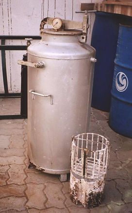
Old Carbide Generator. Description
For many years I have wanted to get my hands on one of these units - as in UK where I come from the charges for renting acetylene cylinders is really exorbitant, especially for someone who only uses acetylene infrequently.
I live in the United Arab Emirates and here there are many small exhaust repair shops still using them. They will not part with them either, so they must be satisfactory. They have been banned in a couple of the other Emirates and this might be a reflection of their dangerous properties or it might be the political power of the acetylene bulk suppliers.
When passing through one of the places where they are banned, I saw recently an old one not in use. After a deal of haggling I got it and brought it home to restore, (it cost me about 90 US$!) It is basically a cylinder of about 16 inches diameter and 3 feet high. It has about 3/4 of the cylinder at the top end double skinned and sealed at the top. It appears to be open into the main cylinder at the bottom and I would think this is where the water goes, so that the level falls away from the carbide which is stored in a basket, raised and lowered by an external lever passing through both skins at the top, when the basket is lowered into the water and gas pressure is raised. There is a line inside to indicate the suitable level.
As soon as I got it home I dismantled it a bit and I had already scraped down and repainted the Flame Trap, which is now a tasteful black gloss. I also cleaned up the lovely brass pressure gauge and the pressure relief valve that you cannot see, it's the other side of the lid to the pressure gauge! What you can see is the rust scale at the bottom of the vessel, which proved to be worse than I expected.
View from other side, note the baskets for the carbide and sludge.
One thing that worries me a bit is the sealing between the two areas where the shaft of the raising/lowering mechanism passes through. The outside seal is a compressed O ring, but I cannot see what seals the inner skin at this point. 14-2-04. I can now! I took it all out and there is a sleeve that passes through both skins and the seal is on the outside only. The whole of the outer chamber seems to be full of carbide residue that looks like chalk, and I would like suggestions as to what would dissolve it, without dissolving the tank, as it is pretty inaccessible. The challenge of restoring this was as much of a motivation as the use to which it will be put. I have restored a lot of old engines, and am still looking for a high pressure diesel fuel pump for a horizontal twin Witte of about 1950 vintage and about 20 HP. I have a fairly extensive home workshop in UK, but some of the items would bring howls of anguish from the Safety Inspectors! I feel the acetylene generator will join these.
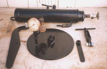
These are a few of the "bits" that have - where appropriate, ended up black I had to make a new top and fix the clamping arrangement for it as it was a bit rusty and would not have sealed properly. I managed to find a piece of rubber sheet from a Rubber Sheet Supplier in Sharjah - Reem Rubber Industries, I also got a guided tour round their factory, which processes raw rubber (latex) right though to producing rubber sheets, blocks etc. of all sizes shapes and specifications. Their plant Manager Mr. Jawed Sajid, could not have been more helpful. The piece I fixed to the new lid which is about 5/16ths of an inch thick steel was about 5 mm. thick and seals perfectly. I stuck it on with contact adhesive.
When the gas is generated it comes out of a union at the top and goes through a valve into a water flame trap cylinder of a couple of inches thick and about 18 inches long mounted on the side and half full of water. Then it goes to the acetylene pipe and the torch. The top of the main cylinder has a thick mild steel plate that clamps on with a thick rubber gasket to seal it. In this plate is mounted a pressure gauge and a safety valve. The pressure gauge goes up to 40 PSI (in German), but I would not dream of using it at this pressure and, because of the rust on the bottom of the cylinder I am going to have it sand blasted and then decide whether to repair any leaks or replace the bottom domed section. I shall then test it to about 40 PSI with water and set the pressure relief to about 15.
In UK I still have a can of carbide that I bought about 40 years ago, It is still OK in it's sealed tin, but it is freely available here at about a dollar a kilo. I have an oxy-propane set up for bronze welding and cutting, but acetylene is better and I want to do sheet steel welding. I would think the trick will be to make it all gas tight, as otherwise I will waste a lot every time I want to use it. When first used, how much gas should be allowed to escape to ensure all the air is purged? Are there any other things to watch out for? Any advice or hints as well as answers to my questions above would be appreciated.
When I was cleaning the bottom, I decided that it was too badly rusted to use, so I cut it off. I was glad I did as on opening it up I found that the whole of the outer casing was full of chalk. - absolutely choked up, - full to the top. I got it all out and then had to find something to use as a domed bottom section. I tried bronze welding all the deep rust scale thin bits, but in the end scrapped it. You can see the shaft that supports the baskets that slide up and down, held at the top and bottom. This is the view from the bottom.
My wife said she had an old steel Wok she did not want any more and as it turned out, it is about the same thickness and it is exactly the right size to fit on instead of the rusted bottom. This is the next job and the shaft that raises and lowers the carbide basket has to be picked up after being re-surfaced as it was worn where the seal has to go. The attempt I made to fill the worn area with bronze is shown, but it kept running and I gave up in the end.
Afterwards I was experimenting with my Oxy-Propane and I found I could just about weld with mild steel wire, so really I should have tried to do that, but by then I had taken it to a little workshop already! You can see the shaft below - together with the many bronze leak filling attempts. The welding and turning proved successful and the shaft seals very effectively now.
Brazing the bottom back on proved to be a problem. The bronze was full of little bubbles and the first time I got it under pressure again to test my welding - air came out all round it. I did it all again more carfully and there was only one or two leaks which I puddled again and ground it all a bit flat and gave it a coat of undercoat. The drain at the bottom was also difficult. I welded a galvanised iron, one inch water pipe fitting into the centre of the wok and this sheared off when I tried to tighten a plug into it. I used a lower temperature and avoided making the next fitting red hot and ended up with a much more satisfactory joint, plus a fitting that was not weakened.
Now I have had it up to 20 PSI. and I am quite happy that when the undercoat and top coat has been applied to the whole tank, it will hold pressure indefinitely. There are still a few pin holes in some of my welds, but the paint will close them in my experience. Even now it holds pressure for several hours.
The next photos will show it, together with the stand I made to clamp round the bottom of the tank. The legs that used to support it were discarded with the bottom rusty section of the tank.
It's starting to look good! I love the Vermillion colour. I found an old tin many years old that I did not know I had, so I am using that up.
You can see from the pressure gauge that it has pressure in it. I pumped it up to 20 PSI and after many remakes of joints and re-welds of bubble holes, I finally got it as airtight as I think I can. It held 20 PSI for a couple of days and I noticed that it went up in the day and down at night as the temperature varied. It is now down to about 15 PSI - several weeks later, which is about what I think it should be and so I am going to adjust the safety valve to this, so it does not get any higher. I just need to re-fit the flame trap and the basket inside for the carbide and debris.
We have just decided that we are going to go back to UK for a holiday in a few weeks so It will probably stay there until we get back. It will be a good chance to see if the pressure holds that long. Now the next problem is a source of Oxygen. Electrolysis sounds good. Any advice anyone?


This is the later version of the PAZ1, mine has a smooth rounder tank, which is slightly smaller, but it is almost identical apart from this.